SS Mount Clay: Historic Deck Plans, Ship Design and the Conversion of a German Ocean Liner
Long before modern cruise ships introduced sprawling entertainment decks, specialty restaurants and balcony accommodations, passenger steamships were undergoing their own remarkable transformations. One particularly interesting example is the SS Mount Clay, a German-built steamship that was converted into an American passenger vessel following World War I.
Originally named Prinz Eitel Friedrich and later known as DeKalb, the ship had already experienced an extraordinary career before being redesigned to accommodate civilian passengers.
A detailed article published in the January 1921 issue of Marine Engineering, titled Passenger Steamship Mount Clay, provides a fascinating look at this conversion. Written by naval architect James A. Kelley, the article includes historical photographs, original deck plans, structural drawings, passenger accommodations and technical specifications.
The five historical images reproduced below offer an opportunity to explore how a large ocean-going steamship was arranged more than a century ago, from its passenger dining rooms and promenade decks to its coal bunkers, machinery spaces and lifeboats.
For readers interested in maritime history, CruisePrism also explores related subjects such as [historic ocean liners], [ocean liner deck plans], [the evolution of cruise ship design] and [classic passenger ship accommodations].
From Prinz Eitel Friedrich to SS Mount Clay
The history of the Mount Clay began in Germany, where the vessel was constructed in 1904 at the Vulcan Works in Stettin.
Originally named Prinz Eitel Friedrich, the ship was built during an era when steam-powered passenger vessels were important links between continents.
Its history changed dramatically during World War I.
According to the January 1921 engineering article, the vessel was taken over by the United States government at the beginning of the war and subsequently served as an Army transport under the name DeKalb.
Following its military service, the ship was selected for conversion into a passenger vessel.
This was not simply a matter of repainting the hull or rearranging a few cabins. The project involved adapting a former German steamship, which had also served as a military transport, to carry a large number of civilian passengers.
The conversion was undertaken at the Morse Dry Dock & Repair Company in Brooklyn, New York.
The original engineering article describes the project as one of the largest steamship reconversion contracts undertaken in the United States up to that time.
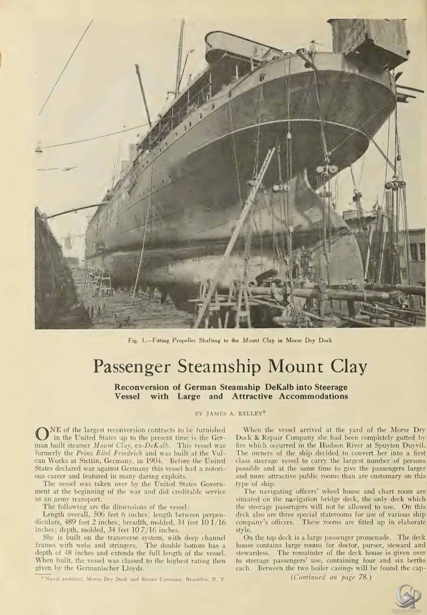
A Historic Photograph of Mount Clay in Dry Dock
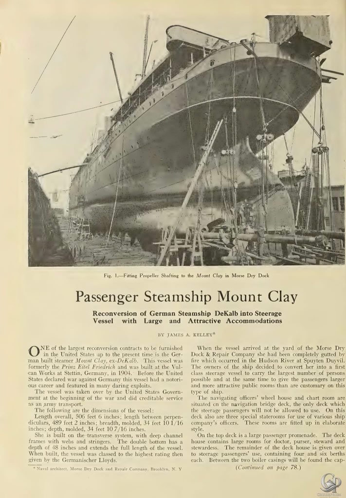
The opening photograph shows Mount Clay elevated in dry dock, with the enormous hull towering above workers, scaffolding and shipyard equipment.
The original caption identifies the work being performed as the fitting of propeller shafting.
The image is particularly valuable because it shows a part of the vessel that passengers would never ordinarily see.
With the ship out of the water, its underwater hull, stern structure and machinery-related fittings were accessible for inspection and repair.
The photograph also illustrates the scale of early twentieth-century shipbuilding. Even without the towering superstructures associated with modern cruise ships, Mount Clay was a substantial vessel requiring extensive industrial infrastructure to maintain and modify.
SS Mount Clay Dimensions and Technical Specifications
The original article provides detailed measurements of the ship.
These figures help establish just how large Mount Clay was for a vessel constructed in 1904.
Principal dimensions and specifications:
- Original construction: 1904
- Shipyard: Vulcan Works, Stettin, Germany
- Original name: Prinz Eitel Friedrich
- Later names: DeKalb and Mount Clay
- Overall length: 506 feet 6 inches
- Length between perpendiculars: 489 feet 2 inches
- Molded breadth: 54 feet 10 1/16 inches
- Molded depth: 34 feet 10 7/16 inches
- Draft: 27 feet 8½ inches
- Displacement: 15,200 tons
- Propulsion: Twin-screw steam machinery
- Main engines: Two reciprocating steam engines
- Indicated horsepower: 4,000 per engine
- Coal bunker capacity: 3,701 tons
The ship also featured a double bottom extending along its length, with a depth of 48 inches.
Its construction used a transverse framing system reinforced by deep channel frames, webs and stringers.
These details are particularly interesting when examining the original structural drawings later in this article.
Original SS Mount Clay Deck Plans and Side Profile
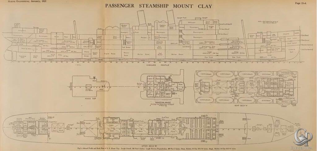
One of the most remarkable surviving illustrations from the engineering article is the large foldout drawing showing Mount Clay’s internal profile and upper deck arrangements.
Published as page 22-A of Marine Engineering, the drawing provides several different views of the ship.
These include:
- A longitudinal inboard profile showing the ship’s internal arrangement
- A plan of the house top
- The navigating bridge
- Boat Deck A
- Upper Deck B
Together, these drawings reveal how the vessel’s passenger accommodations, crew facilities, navigation spaces and machinery were distributed throughout the hull.
Unlike modern cruise ship deck plans, which primarily help passengers locate cabins, restaurants and entertainment venues, these engineering drawings also document the ship’s working infrastructure.
Coal bunkers, boiler rooms, engine rooms, ventilation trunks and storage compartments appear alongside passenger spaces.
The Navigating Bridge
The navigating bridge occupied an elevated position, giving the ship’s officers a commanding view.
The drawing identifies the wheelhouse, chart room and officers’ accommodations.
The accompanying article explains that the navigation bridge deck was reserved for officers and was not accessible to steerage passengers.
This arrangement reflected the operational and social divisions common aboard passenger ships of the period.
The Boat Deck and Lifeboats
The boat deck drawing shows lifeboats arranged along both sides of the ship.
The January 1921 article explains that providing sufficient lifesaving equipment required careful planning because of the limited space available.
The vessel carried several types of lifeboats, including motorized and conventional boats.
The published specifications identify:
- One 24-foot standard motor Welin lifeboat
- One 24-person standard Welin lifeboat
- Two 26-foot standard Welin lifeboats
- Ten 28-foot standard Welin lifeboats
- Fourteen 28-foot Broady 2-a lifeboats
These boats provided accommodation for 1,613 people.
The article also identifies two cylindrical life rafts with capacity for 25 people each, bringing the total stated lifesaving capacity to 1,663.
This was intended to accommodate the vessel’s planned complement of 1,452 passengers and 211 crew members.
Passenger Accommodations and the Different Decks
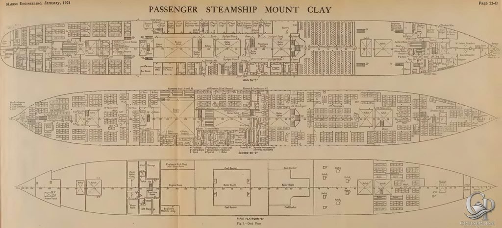
The second foldout drawing, published as page 22-B, provides an even more detailed look at the internal layout.
It includes three principal deck plans:
- Main Deck C
- Second Deck D
- First Platform E
These drawings are especially revealing because they show the enormous difference between passenger accommodations in the early twentieth century and those found aboard modern cruise ships.
First-Class Passenger Spaces
The original article explains that the owners wanted to convert the vessel into a first-class passenger ship capable of carrying as many people as possible while providing larger and more attractive public rooms.
The planned passenger facilities included dining saloons, sitting rooms and a promenade deck.
The upper dining saloon had a seating capacity of 140 people and was finished in paneled oak.
A women’s sitting room was located aft of this dining space, also featuring paneled oak and upholstered seating.
These rooms represented the more comfortable side of passenger travel aboard Mount Clay.
Steerage Accommodations
A substantial portion of the ship was devoted to steerage passengers.
The article specifically describes large holds on the second deck that were arranged to accommodate passengers but could also be used for cargo if required.
This dual-purpose arrangement was an important feature of the vessel’s conversion.
Rather than dedicating every available space permanently to passenger cabins, the ship retained some flexibility between transporting people and carrying freight.
The deck plans show densely arranged sleeping accommodations, passageways, toilets and other shared facilities.
The contrast with modern cruise ship cabins is striking.
Crew Accommodations and Working Areas
The drawings also identify numerous spaces reserved for the crew and ship operations.
These include:
- Crew quarters
- Officers’ accommodations
- Engineers’ quarters
- Galleys
- Storage rooms
- Hospital facilities
- Coal bunkers
- Machinery compartments
The original article notes that the lower dining room had seating for 334 people and was finished with paneled oak.
It also identifies a barroom on the starboard side of the after-well deck and a dispensary on the port side.
These details help illustrate the range of facilities required aboard a passenger steamship carrying more than a thousand people.
How the Mount Clay’s Hull Was Constructed
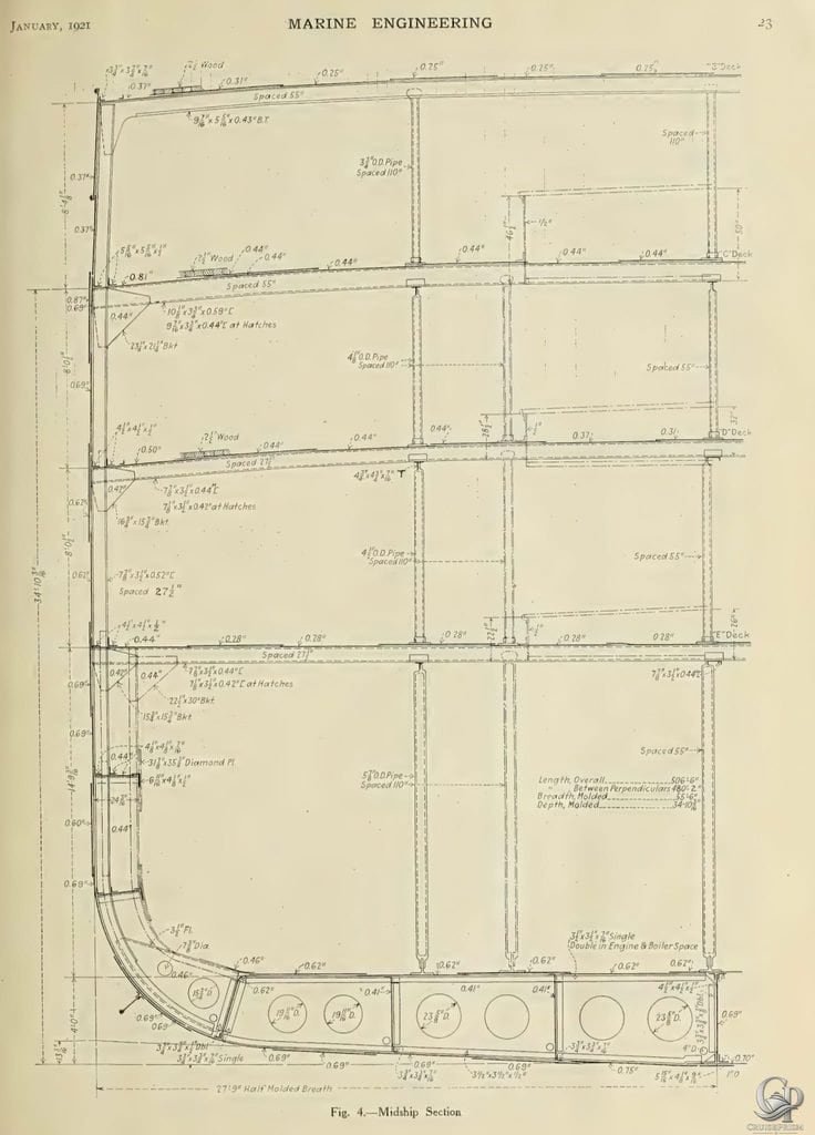
The fourth historical image is a detailed structural drawing identified as Fig. 4, Midship Section.
Published on page 23 of Marine Engineering, it shows the internal construction of the hull.
Rather than presenting passenger accommodations, this illustration concentrates on the steel framework that supported the ship.
The drawing includes measurements and specifications for:
- Hull plating
- Deck plating
- Structural beams
- Vertical supports
- Frames and brackets
- Double-bottom construction
- Connections between decks and hull structures
The midship section is particularly useful for understanding how shipbuilders created large, multi-deck steel vessels before modern computer-aided design.
Every major structural element had to be carefully calculated and documented.
Why the Double Bottom Was Important
Mount Clay’s double-bottom construction provided a space between the outer hull plating and the inner bottom structure.
According to the engineering article, the double bottom could carry 988 tons of salt-water ballast.
Ballast was important for controlling a vessel’s draft, trim and stability under different loading conditions.
The ship also had freshwater storage capacity within its double-bottom tanks.
These internal arrangements demonstrate how the hull itself was used for more than simply keeping the ship afloat.
Steam Engines, Boilers and Propulsion
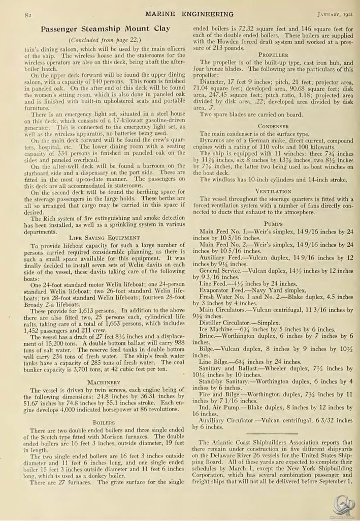
The final page of the historical article provides extensive technical information about Mount Clay’s propulsion machinery and onboard systems.
For readers interested in historic ocean liners, this is one of the most fascinating parts of the original documentation.
Mount Clay was powered by two reciprocating steam engines driving twin propellers.
Each engine was rated at approximately 4,000 indicated horsepower at 86 revolutions per minute.
The ship used coal-fired boilers to generate the steam needed to operate its engines.
Boilers and Coal Consumption Infrastructure
The article identifies two double-ended boilers and three single-ended boilers.
It also specifies a total of 27 furnaces.
The double-ended boilers measured 16 feet 3 inches in outside diameter and 19 feet in length.
The boilers used a Howden forced-draft system and operated at a pressure of 213 pounds.
Coal storage was another major consideration.
Mount Clay’s coal bunkers had a capacity of 3,701 tons.
The deck plans show how these bunkers occupied considerable space around the ship’s machinery compartments.
This is one of the fundamental differences between early steamships and modern cruise vessels: large amounts of internal volume had to be devoted to coal storage, boilers and the equipment needed to operate them.
The Propellers
The original article describes the propellers as built-up assemblies with cast-iron hubs and four bronze blades.
Their specifications included:
- Diameter: 17 feet 9 inches
- Pitch: 21 feet
- Number of blades: Four per propeller
- Construction: Cast-iron hub with bronze blades
- Spare blades: Two carried aboard
The photograph of the ship in dry dock provides a useful visual connection to these technical details.
Safety, Ventilation and Passenger Services
The conversion involved more than installing passenger accommodations.
The January 1921 article also describes systems intended to support the health, safety and comfort of those aboard.
Fire Protection
Mount Clay was fitted with a Rich fire-extinguishing and smoke-detection system.
Sprinklers were also installed in various compartments.
Fire prevention was particularly important aboard a steamship containing coal-fired machinery, passenger accommodations, galleys and extensive internal passageways.
Ventilation
The steerage quarters were equipped with a forced-ventilation system.
Fans connected to ducts exhausted air to the atmosphere.
This was especially important in the densely occupied passenger spaces shown in the deck plans.
Freshwater and Emergency Power
The article identifies freshwater storage tanks with a capacity of 285 tons, along with additional reserve feed-water storage.
It also describes an emergency lighting system powered by a 17-kilowatt gasoline-driven generator.
The generator supplied emergency lighting and wireless equipment without relying on batteries.
These details illustrate how passenger ships were incorporating increasingly sophisticated electrical and mechanical systems during the early twentieth century.
What Makes These Historic Deck Plans So Interesting?
For modern cruise enthusiasts, perhaps the most interesting aspect of the Mount Clay drawings is how clearly they illustrate the evolution of passenger ship design.
Today’s cruise ships are generally organized around passenger amenities, entertainment venues, restaurants, cabins and recreational facilities.
Mount Clay’s plans reveal a very different set of priorities.
The ship needed to accommodate a large number of passengers while also providing substantial space for steam machinery, coal, cargo, crew operations and essential services.
Several differences stand out:
- Passenger density: Large shared sleeping areas occupied substantial sections of the lower decks.
- Dining arrangements: Separate dining spaces served different groups aboard the vessel.
- Promenade areas: Outdoor promenades provided an important recreational space.
- Machinery requirements: Coal bunkers and boiler rooms occupied considerable internal volume.
- Cargo flexibility: Some passenger spaces could be converted for freight transportation.
- Lifesaving equipment: Lifeboats were distributed along the boat deck, requiring careful allocation of limited space.
These features make the Mount Clay plans valuable not only to maritime historians but also to anyone interested in how modern cruise ships developed from earlier generations of passenger vessels.
Frequently Asked Questions About SS Mount Clay
What was the SS Mount Clay originally called?
The ship was originally named Prinz Eitel Friedrich. It later served as DeKalb before being converted into the passenger steamship Mount Clay.
When was Mount Clay built?
The vessel was constructed in 1904 at the Vulcan Works in Stettin, Germany.
How long was the SS Mount Clay?
The January 1921 engineering article lists an overall length of 506 feet 6 inches.
How many passengers could Mount Clay carry?
The published conversion specifications identify accommodations for 1,452 passengers, along with a crew of 211.
Was Mount Clay powered by steam?
Yes. The vessel used twin reciprocating steam engines powered by coal-fired boilers. Each engine developed approximately 4,000 indicated horsepower.
Did Mount Clay have first-class accommodations?
Yes. The conversion included more attractive public rooms, dining facilities and passenger accommodations intended to support first-class travel.
The plans also show extensive steerage accommodations.
How many lifeboats did Mount Clay carry?
The January 1921 article lists 28 lifeboats of various types, together with two additional cylindrical life rafts.
The total stated lifesaving capacity was 1,663 people.
Where was Mount Clay converted into a passenger ship?
The conversion was carried out at the Morse Dry Dock & Repair Company in Brooklyn, New York.
Where did these original Mount Clay deck plans come from?
The plans appeared in the January 1921 issue of Marine Engineering, accompanying an article by James A. Kelley titled Passenger Steamship Mount Clay.
The published drawings include an inboard profile, navigating bridge, boat deck, upper deck, main deck, second deck, first platform and midship structural section.

Conclusion
The SS Mount Clay represents a fascinating chapter in the transition from early twentieth-century ocean liners to the modern passenger ship.
Originally built in Germany in 1904, the vessel experienced military service before undergoing an extensive conversion into a civilian passenger steamship.
The surviving January 1921 engineering drawings provide an unusually detailed view of this transformation.
From its oak-paneled dining rooms and large steerage compartments to its coal-fired boilers, twin propellers and elaborate structural framework, Mount Clay illustrates the engineering challenges involved in accommodating more than 1,400 passengers aboard a steam-powered vessel.
For anyone interested in historic ocean liners, vintage ship deck plans or the evolution of cruise ship design, these documents offer a remarkable glimpse into a very different era of travel at sea.